**This exercise is done partially since we do not have any fab lab machines here at fab lab addis**
According to the specification given during the conference, I made a schematic drawing of a circuit by making use of Eagle software. we where suppose to add some additional component to the circute design given to us, so I added a switch to my circute design.
The drawing is shown on the figures/pictures below.
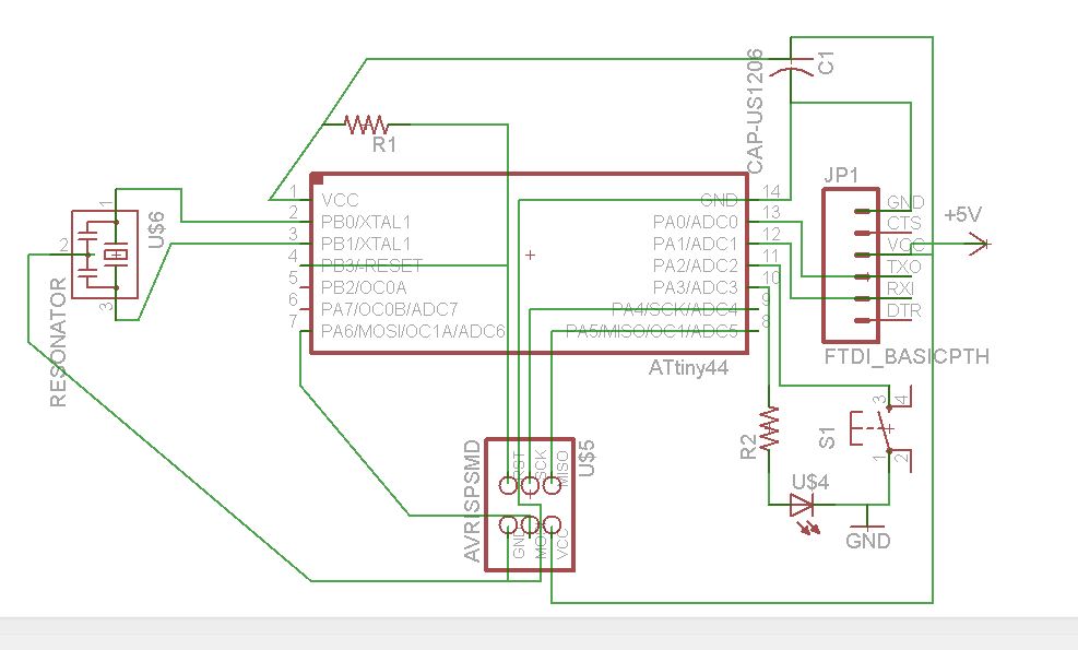
picture showing the schematic drawing of the circute drawing
After making the schematic drawing of the circuit board, I move on to making the board look realistic in the board media of the eagle software. And the fallowing drawing was the outcome.
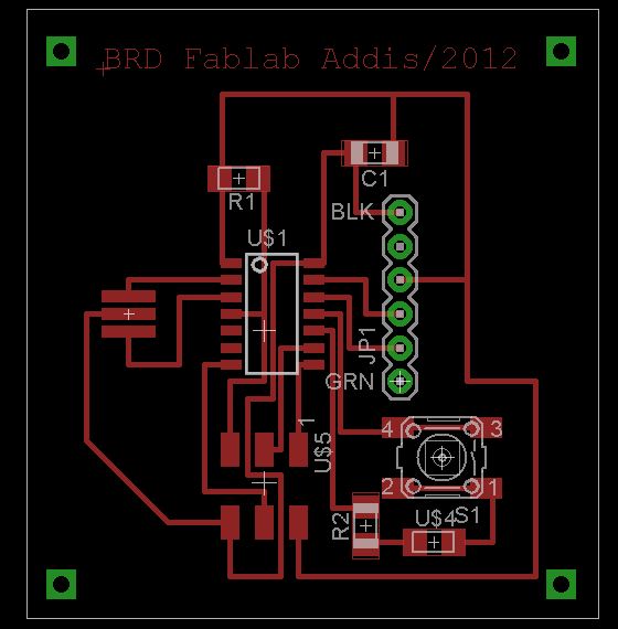
After the board diagram is prepared like shown in the above picture, I prepared additional two drawings: one for the body of the board and another for the boarder
Board drawing ready for machining of body and boarder line of the circut board. As shown in the picture above, I made four holes at four corners assuming that the board will be screwed to other components.
|
